|
|
Tutorial: Pounamu installation and configuration
back to head1. Install pounamu software:
1) Make sure in your machine, JDK1.4.0 has been installed.
2) Unzip the download pounamu.zip file to wherever in your machine.
3) Move the "compile_and_run_pounamu.bat" file to the same folder where pounamu folder is in.
4) Edit the "compile_and_run_pounamu.bat" file, change the path before "javac" and "java" to the right path to "javac" and "java" in your machine.

2. Configure pouanmu:
1) Run pounamu by executing "compile_and_run_pounamu.bat".
2) In the tree panel, click the node "pouanmu".
3) Click the menu "pounamu" in the menu bar, or right click anywhere on the tree panel, then in the menu click the "confiure this tool" item.
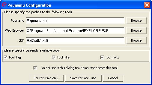
4) A dialog box will pop up. Input or "choose by browsing" the right full paths to the pounamu folder, Web Browser and JDK in your machine.
5) In the available tools area, the tools created and registered before are shown. Select them if you want to use them or deselect them if you do not want to use them any more.
6) Check the box "Do not show..." if you do not want to configure pounamu on your machine again.
7) Click "save for later use" button if you want to save your configuration for later use. Click "for this time only" button if you just want to make the configuration effective for this time only. Click "cancel" button to cancel the configuration.
Pounamu is a MetaCASE/CASE tool. You can use it to create your own tool, or you can use it to model a real-world case. In both cases, you need to define lots of objects. These objects can be as "big" as a tool which is what you want, a model which is the result of your modelling using your own created tool, or as "small" as a visual component used to create a visual icon. Pounamu itself, as a whole, is an object.
There are two kinds of objects in Pounamu. One kind are pre-defined objects, such as the tool project manager, model project manager, shape creator, connector creator, handler definer, metamodel definer, view type definer and pounamu itself; another kind are user-defined objects, such as shapes, connectors, handlers, views, view types, entity types, association types, entities and associations.
All pre-defined objects have a given name which begins with a lower case letter and is unchangeable. For example "pounamu" for Pounamu itself, or "tool projects" for the tool project manager.
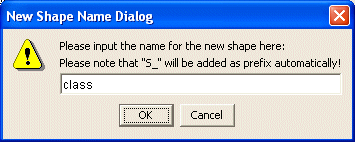
All user-defined objects have a name given by user. However to manager the names well, Pounamu automatically adds the object type to the user given name as a prefix, and changes the first letter of the user given name to upper case. For example, if you want to create a new shape, you give a name "class" to this shape, then Pounamu will change this name to "S_Class", "S_" is the object type for all shape objects. Please note that when there is a dialog box asking you to input the name of an object, do not input the part which will be automatically added, like "S-".
The common types in Pounamu naming system is listed here:
|
Type |
Object |
| S | shape |
| C | connector |
| H | Handler |
| ET | entity type |
| AT | association type |
| MMV | metamodel view |
| VT | view type |
| Tool | tool |
| Model | model |
To manage all objects, Pounamu uses a tree, called the manager tree. It is located in the middle left panel of the main user interface. Each object, predefined or user_defined, will have an entry in the this tree, where its name will be showed as a node. The tree automatically expands, adding nodes, when a new object is created, and shrinks, deleting nodes, when a object is removed.
Before you do anything, you have to decide which object you want to work with. As the manager tree has listed all existing objects, you may easily select an object by selecting the node on the tree which displays the object name. The selected object will be the so-called "working object". At anytime, there is only one node that can be selected, therefore there is only one working object. Once a working object is selected, the viewing area, which is the main area located in the centre of the main interface, will show its visual icon (if it has any), the property area, located in the middle right area of the main interface will show its properties (if it has any), and the menu (and popup menu) will show all available functions that can be performed on this object.
As there are so many types of objects inside Pounamu, and there are many functions can be applied to each type of object, it is hard for a user to find the right functions which can be applied to the working object if there is not a good way to arrange menus. Pounamu make it simple for user to select functions by using "smart menu". In Pounamu interface, the menu area only has two menus. One is for help, another one is the so_called "smart menu" named "pounamu". When you select a working object from the manager tree, all available functions for this working object will be shown in the "smart menu". Its twin, a popup menu which has the exactly the same list of menu items, is also available for users who like "right clicking" mouse.
Once an object is selected from the manager tree, if it has any properties "exported" to the user, the properties will be shown in the property area. The properties are arranged in a table. This table can be used to both view and edit properties and hence configure the object. If the object has no property to be shown, the property area will be empty.
Pounamu is a kind of visual programming tool. Therefore most of objects in Pounamu have icons as visual representations. Once an object is selected from the manager tree, if it has a visual icon, the icon will be shown in the viewing area of the main interface. The viewing area is managed with a four_level structure. The base level use a tabbed pane to hold each project pane. The second level uses a tabbed pane to hold all view types in the project. The third level uses a tabbed pane to hold all views in this view type, and the fourth level is a panel to show icons. For example, if you select a shape object "S_Class" in the tree panel, the node "S_Class" has a parent node "shape creator" and parent-parent node "Tool-UML", then the viewing area will show a tabbed pane which contains "Tool_UML" as its base pane, then inside this pane is the tabbed pane "shape creator" which contains all created shapes, then in that tabbed pane, is displayed the panel which contains shape "S_Class" and in that panel, the icon for "S_Class" is shown as selected. The levels of the viewing area have been mapped to the levels of the tree node. So any change to either of them will cause a corresponding change to the other one.
When you have chosen a working object, and also have selected a function from the menu, if there is nothing happening, do not panic! You will be told what is going on behind the interface. What you need to do is move down to the lower part of the main interface, where there is a tabbed pane, clicking the "general" tab if it is not currently shown, then read the information shown. Then you know what is happening, even what is wrong.
If you are using the tool you created to model a project, whenever there is something wrong, you may be able to undo it. The undo / redo lists are nested in the same tabbed pane with general information. You may undo/redo an operation at any time. Please note that, at most times, undoing the latest operation is safe, but undo/redo of an operation deeper in the undo/redo history may cause errors. The undo / redo part works in model project only currently.
Any user-defined objects can be saved into xml files and then reloaded whenever you want to reuse it. The file name will be the same as it appears in the tree. All saved files will be automatically put into the "tools" folder under pounamu folder except the handlers which go to "handler" folder. Please note that there are some "conditions" to load some saved files, for example, if you try to load a "view" file, then the tool which create this view must be the current tool. Trying to reload a view created by "Tool_UML" into a project using "Tool_Architecture" will cause an error.
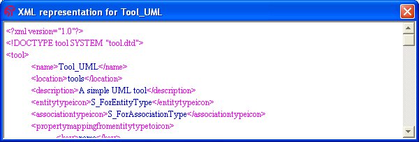
At anytime, if you want to check what information is included in the objects you created, you have two options to do so. One is clicking the corresponding node, then checking the property table shown in the property area. As all properties are listed there, you may easily inspect available information. Another way is by selecting the "view xml file" option from the menu, then in the popup xml pane, you may view the whole xml file for this object.
Pounamu supports both multiple view types and multiple views. Multiple view types means we can have different view types in a model. For example, in a UML tool, we have "class diagram" view type, "Use cases" view type and "sequence diagram" view type etc. Multiple views means we can have more than one window (view) in each of the view types. This is extremely useful when a diagram is getting too big for a view -- we can cut it into several windows thus make each window tidy and elegant.
In Pounamu, an object can appear in different views of different view types. It can appear with a different icon in the different view types, but it has the same icon in the views of the same type. All icons in the views of the different view types are "sharing" the same object. Pounamu has facilities to handle coordination among them.
Tutorial: Using Pounamu to create a simple UML tool
back to head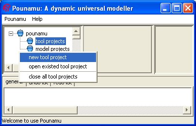
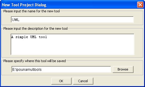
1) Click the "tool project" node in the manager tree, then in the menu (either the menu "pounamu" in the menu bar or the popup menu accessed by right clicking anywhere in the tree panel) click the "new tool project". In the popup new tool project dialog, enter "UML" for the name of this tool (pounamu will add "Tool_" to it as prefix and change the first letter to upper case). You may enter a description in the description area or leave it empty. You should now leave the location field unchanged (for now pounamu now uses it as default folder to store any objects from tool creation or modelling). Click the "ok" button.
2) Now in the manager tree you have a "Tool_UML" node with 5 child nodes. In the main viewing area you have the tabbed pane for "Tool_UML" which contains 5 tabbed panes corresponding to the nodes.
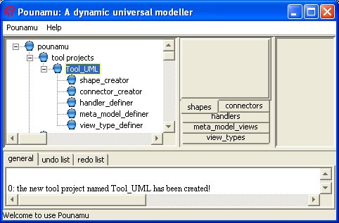
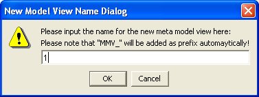
3) Click "meta_model_definer" node in the tree, and then in the menu select "open a new view". In the popup name dialog, enter "1" ("MMV_" will be added to it). Click the "ok" button.
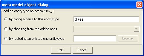
4) In the tree, the node "MMV_1" is added and selected and the tabbed pane of "meta_model_views" is set to be the current pane. In the menu, select "add an entity type", then in the popup dialog, select the "by given a name to this entity type" radio button. Enter "class" (pounamu will make it "ET_Class"). Click the "ok" button.
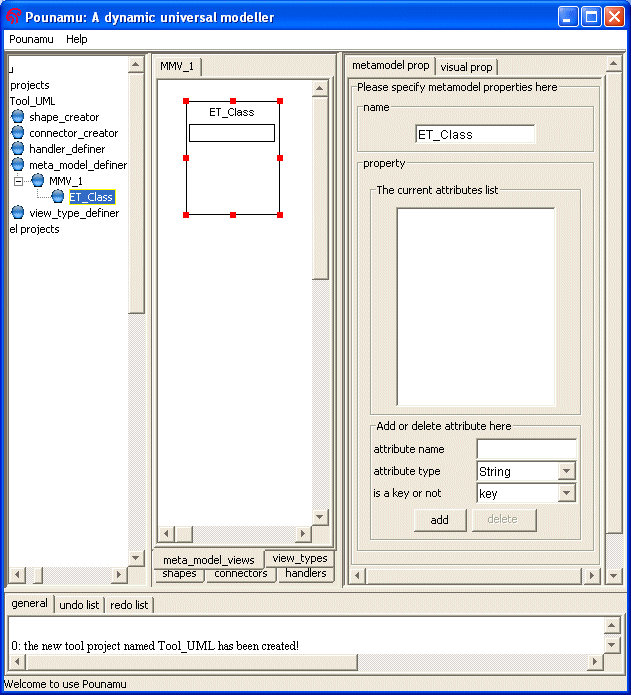
5) Nothing happens! Do not panic. As you are asked to specify the position of this entity type icon. So in the viewing area, click where you want the icon to be. A icon appears where you clicked. and a property table is shown in the property area.
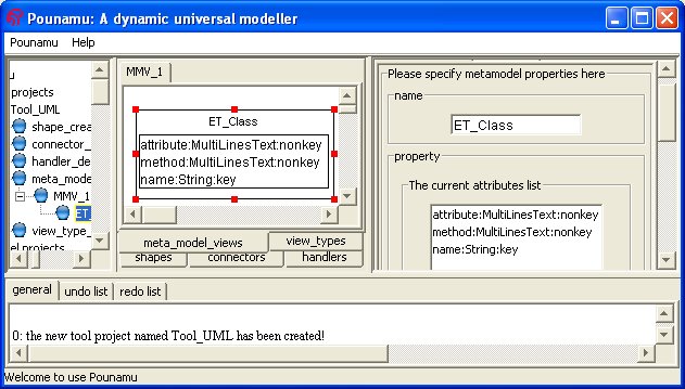
6) In the property table, we enter three attributes "name, String, key", "attribute, Multilinesinput, nonkey" and "method, multilinesinput, nonkey". Click the "ok" button. (Please note that the properties will not be updated if you do not click "ok"). In the icon, you will see these attributes. If you are not satisfied with what you have entered, you may use the property table to reedit them.
7) In the menu (you know where it is or how to bring it up:-)), select the "register this entity type" item. This entity type is created! You may also click corresponding items in the menu to view xml files, to save files. But if you want to use this entity type later on, you must register it. Registering the entity type also saves it to default folder.
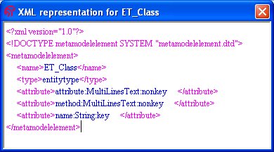
8) Repeat 4) - 7), but click "add an association type". Give the new association type a name "implement" ("AT_Implement" in pounamu). In the property table, input one attribue "label, String, Key". Then register it.
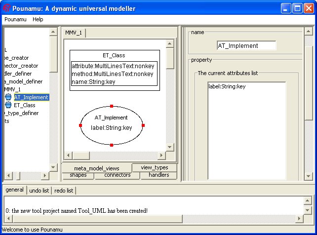
9) If you want to reuse this meta model view later, then click "MMV_1" node, then click the "register this view" button or the "save this view" button.
10) We have an entity type "ET_Class" and an association type "AT_Implement". Now we will choose icons for both. For any entity, we need a shape as icon, and for any association we need a connector as icon.
11)Click the "shape creator" node in the tree. In the menu, click "Create a new shape". In the popup dialog, input "class" ("S_Class" in pounamu).
12) A shape icon appears in the viewing area and the node "S_Class" has been added to the tree with a subnode "S_Class_basepanel" which is selected. The base panel is the contaiing panel of the shape into which we may add additional elements as we need. The property area shows the properties of the base panel.
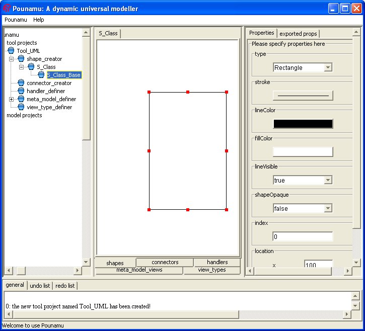
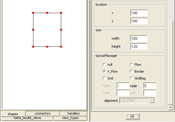
13) In the property table, we change the layout to "V-Flow" with the "vgap" 5. That means we are using vertical flow layout to manager components in this base panel. We also change its size by width = 100, height =120, click "ok" button.
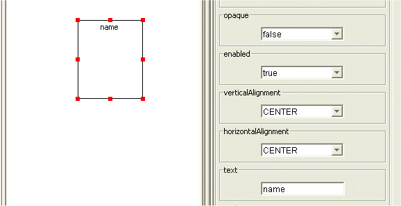
14) In the menu, click "add a label". In the property table change horizontal alignment to "center" and input "name" in "text" field. Switch to the "exported tab" in the property table then click "text" radio button and input "name" in the text field. Then Click ok.
15) Select the base panel again and in the menu select "add a text area". In the property table input "attribute" to the "MultilinesText" field. Switch to the "exported tab" in the property table then click the "MultilinesText" radio button and input "attribute" in the text field. Then Click ok.
16) Add another text area to the base panel. In its property table input "method" to the "MultilinesText" field. Switch to the "exported tab" in the property table then click the "MultilinesText" radio button and input "method" in the text field. Then Click ok.
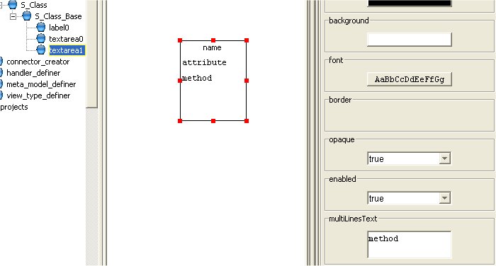
17) Select the "S_Class" node on the tree. In the property area, check if the exported properties are what you want. If not, select the object to change it.
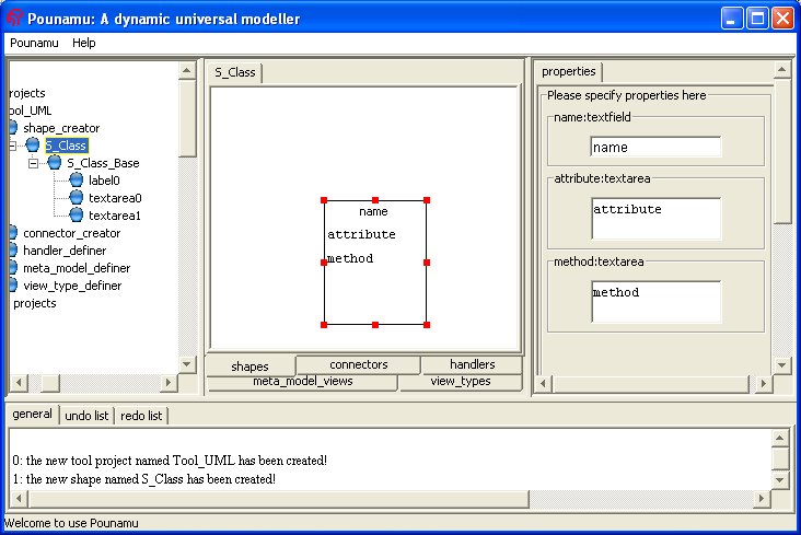
18) Click "S_Class" node in the tree. And in the menu select "register this shape" if you want to use it later on. You may also select "view xml file" to check the information saved in the shape xml file.

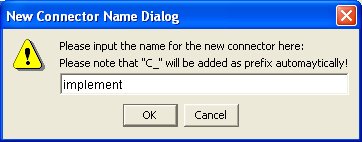
19) Click "connector creator" node on the tree. In the menu, click "Create a new connector". In the popup dialog, input "implement" ("C_Implement" in pounamu).
20) In the property table, select an empty triangle shape for the endShape and input "label" in "middleLabel" field. Switch to "exported tab" and select the "middleLabel" radio button and input "label" in the text field. Click the "ok" button.
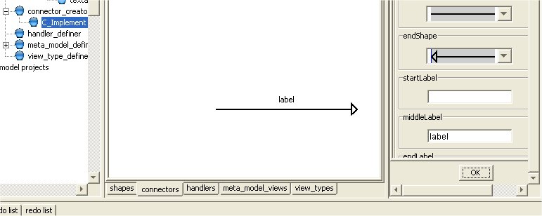
21) Click "C_Implement" node on the tree. And in the menu select "register this connector" if you want to use it later on. You may also select "view xml file" to check the information saved in the connector xml file.

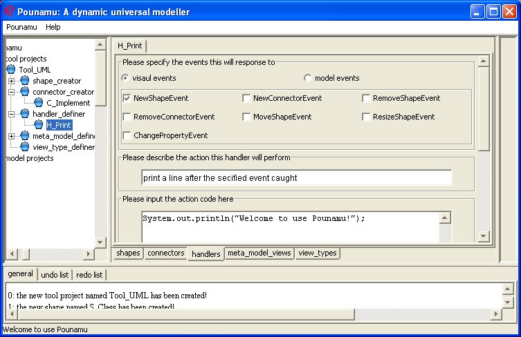
23) We have created one shape, one connector, one entity type and one association type. Now we move to the handler creator to define a handler. On the tree, click the "handler_definer", and in the menu, click "create new handler". Then in the popup dialog, input "print" ("H_Print" in pounamu) in the name field. Click "ok" button.

24) for step 24-25, please see "Tutorial: How to create an event handler". In the handler definition panel, click the "visual event" radio button, then select "NewShapeEvent". You may leave the description area empty at this time and then input the code in the code area. This time, input "System.out.println("Welcome to Pounamu!");"
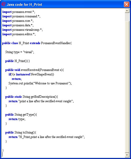
25) In the menu, you may choose "view xml" or "view java code" to check if this handler is what you want, or "generate java code" or "save this handler" ets to save xml file or java code. Or you may click the "register this handler" to perform all these with one go. if there is compilation failure information is displayed in the message area. Just follow the message to debug your code then register the handler again.
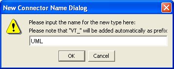
26) Now it is time to define the view type which is a most important part in the tool creation. Click the "view_type_definer" node on the tree. Then in the menu, click "define a new view type" item. In the popup dialog, input "UML" ("VT_UML" in pounamu).
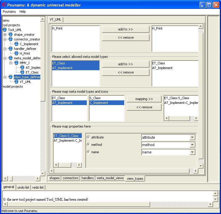
27) In the view type define panel, the available handlers, entity types and association types appear in the right box. What you need to do is select the ones to be used in this tool. First, select "H_Print" from the available box and "add to" allowed handlers box. Then select both "ET_Class" and "AT_Implement" in the available model element box and "add to" allowed meta model element box.
28) Then in the icon mapping area, map "ET_Class" to "S_Class" and then map "AT_Implement" to "C_Implement".
29) Then in the property mapping area, choose a pair from the icon/entity association/connector mappings. A panel with two columns appears. On the left are properties of the model element in the selected pair, on the right are properties of the icon in the selected pair. Choose one on the left and then select one on the right, these two will be mapped to each other. Please note that you do not need to select all properties from the left column, as some of them can be "invisible" to the user, which means they will not be shown in the icon.
30) After you have finished mapping properties for all the chosen pairs. You may click register this view type in the menu. A view type has been defined. Now in "Tool_UML" we have a view type "VT_UML" in which only one entity type, one association type and one handler are allowed.
31)It is time to register the whole tool! Click the "Tool_UML" on the tree, then in the menu, click the "register this tool" option. Check the message window, if there is no error message, the tool is registered successfully and can be later used.
Tutorial: Using the created UML tool to model a simple project
back to headPlease first go through the "Tutorial: Using Pounamu to create a simple UML tool" and create a UML tool with Pounamu.
1) Click the "model project" node in the manager tree and select "new model project" from the menu.
2) In the popup new model project dialog, pull down the available tools combo box and check if there is a tool "Tool_UML" in the list. If there is not such a tool, then click cancel. Click "tool project" node on the tree, and then in the menu click "open existed tool project" item. Browse to "Tool_UML.xml" then click "ok". If you have created the UML tool properly, there should be no problem with loading the tool. Click the the "Tool_UML" node on the tree, then in the menu click "register this tool". Then back to 1).
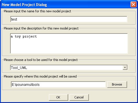
3) In the popup new model project dialog, pull down the available tools combo box and select "Tool_UML" in the list. Then in the name field, input any name you like to name the project, such as "test". You may leave the description empty and the location area unchanged. Click the "ok" button.
4) Now a "Model_Test" has been added to the tree. Under this node, there is child node "VT_UML", meaning that only this view type is allowed in the UML tool. In the viewing area is a tabbed pane named "VT_UML" which will hold all "VT_UML" views.
5) Click the "VT_UML" node and select "open a new VT_UML view" from the menu. In the popup dialog input engter "1". You will see that a node named "VT_UML_1" is added to the tree and a panel with the same name has been added to the tabbed pane.
6) Click "VT_UML_1" node on the tree and then in the menu click "add an object of ET_Class". In the popup dialog, select the first radio button and then input "person" in the text field. Click ok.
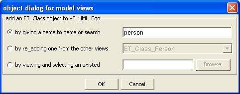
7) Nothing will happenunti you click on the viewing panel where you want to add this object. Then you will see an icon appear there and its property table appear in the property area.
8) In the property fields, input "person" for NAME, and anything for ATTRIBUTE and METHOD. then click ok.
9) Repeat 6)-8), but entering "student" for NAME and anything for ATTRIBUTE and METHOD.
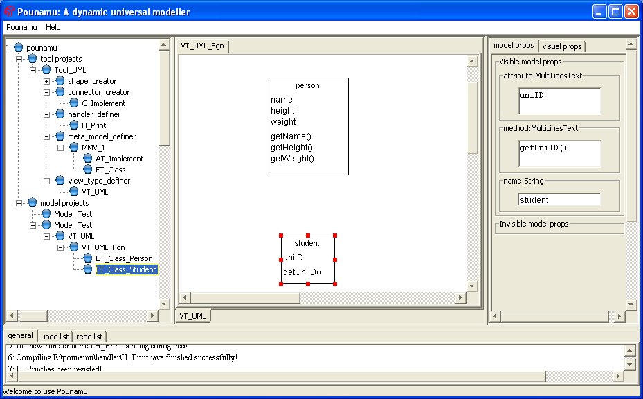
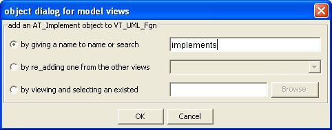
10) Click "VT_UML_1" node on the tree and then in the menu click "add an object of AT_Implement". In the popup dialog, select the first radio button and then input "implements" in the text field. Click ok.
11) All added entity objects will have been selected. Click on one handle of the object which you think is a "child" hold the mouse down and drag to the "parent" object and release on one of its handes. A connector will appear to connect those two shapes and the property table of that association object would be showed in the property area.
12) In the property table, input "implement" in the label field.
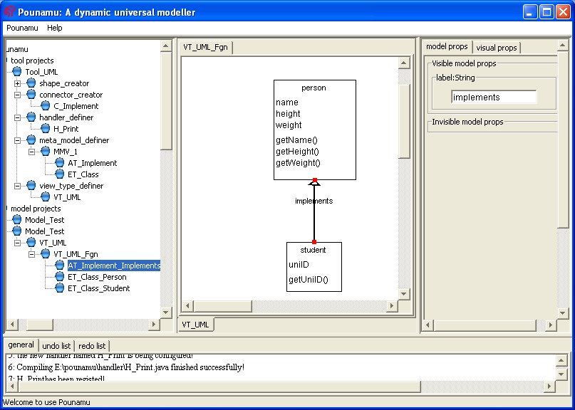
13) Here we finished a simple model. If you are not satisfied with the visual appearance, Click "VT_UML_1" node on the tree and then in the menu click "enter select state", now you are able to move or resize each shape on the panel.
Tutorial: How to create an event handler
1) Overview
2) An example
Here is the interface and contents for a handler definition.
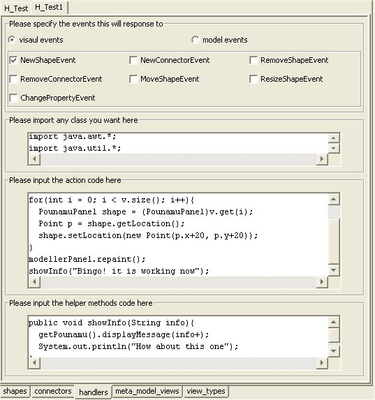
In this example, select "Visual event" from the radio button, and then select "NewShapeEvent" tick box.
In this example, input "import java.awt.*;" and " import java.util.*;".
In this example, input the code which will make all shapes in this panel move right_down.
In this example, one method "showInfo" has been used in the action code, so in "helper method code" area, this whole method has been written.
3) Some useful points
pounamu ----- getPounamu(), the pounamu working instance
manager ----- getManager(), the manager of the pounamu instance
tool ---- getTool(), the tool this model project uses
project ---- getProject(), the model project